Blog
Buyer’s Guide to High-Precision Cutting Lasers

How to choose the right laser cutting system: a practical industrial guide
Laser selection does not start with a model number. It starts with the material, thickness, geometry, edge-quality requirement and cycle time. Even a highly capable source can underperform when its wavelength, pulse regime, optics, motion and extraction are not matched to the process.
This guide helps you narrow the field and prepare meaningful trials. For a production investment, the final selection should be confirmed on representative samples under conditions that closely reflect manufacturing.
| Quick answer For metals and high throughput, start with fiber laser technology. For polymers, wood, paper and many organic materials, evaluate CO₂. For microfeatures and heat-sensitive or brittle materials, compare UV, picosecond and femtosecond options. Then validate the process on real samples. |
When is laser cutting the right choice?
Laser cutting is a non-contact, flexible and repeatable process. It avoids tool wear and allows rapid geometry changes through software. It can produce narrow kerfs, fine details and edges that need little post-processing.
- delicate or thin parts where mechanical forces must be avoided;
- complex geometries, variable batches and rapid prototyping;
- tight requirements for kerf width, heat-affected zone and repeatability;
- processes that need automation, monitoring and production-line connectivity.
Laser processing is not automatically the lowest-cost option. For simple contours in thick material, very high volumes or relaxed tolerances, stamping, mechanical cutting, waterjet or plasma may deliver a better cost per part. Compare capital cost, consumables, maintenance, yield, scrap and secondary operations.
Define the requirement before comparing lasers
| Question | What to specify | Why it matters |
| Material | Composition, coating, pigment, adhesive, treatment | Determines absorption and removal mechanism |
| Thickness | Nominal and tolerance; single or multilayer | Drives power, pulse energy, focus and pass count |
| Geometry | Contour, radii, holes, path density | Sets spot size, motion platform and strategy |
| Quality | Kerf, burr, taper, roughness, HAZ | Creates measurable acceptance criteria |
| Throughput | Cycle time, parts/hour, batch size, target OEE | Sizes the source, motion and automation |
| Integration | Interfaces, vision, fixtures, handling, MES | Turns the source into a production system |
| Safety | System class, enclosure, interlocks, fumes | Shapes architecture, compliance and operation |
| 1 Requirements | 2 Technology selection | 3 Sample trials | 4 Validation | 5 Integration & service |
The main laser cutting technologies
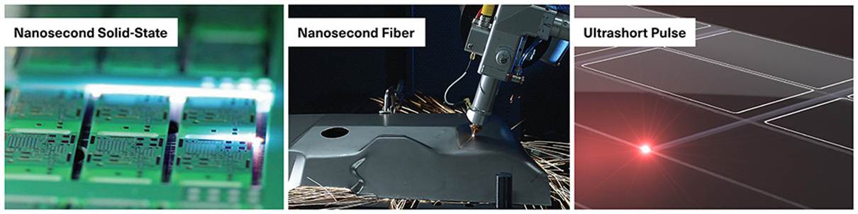
Laser families used for cutting.
| Technology | Best starting point for | Strengths | Limits to validate |
| CW / QCW fiber | Metals; sheet; combined welding/cutting; throughput | Efficiency, high average power, industrial integration | Back-reflection, HAZ, edge quality, assist gas and material compatibility |
| Nanosecond fiber / solid-state | Thin metal, foil, drilling, PCB, selected ceramics | Good pulse-energy control; compact architecture | More thermal effect than ultrashort pulses |
| CO₂ | Polymers, wood, paper, textiles, organic materials; selected composites | Strong 9–11 µm absorption in many non-metals | Pigment, fumes, charring, optics and beam path |
| Nanosecond UV | Polymers, films, electronics, microfeatures | Small spot and good coupling in many materials | Cost, lifetime and throughput must be validated |
| Picosecond / femtosecond | Glass, sapphire, ceramics, sensitive polymers, microelectronics | Low thermal impact and very high precision | Investment, removal rate and process window |
Browse the APEL Laser product range to compare available source families and systems.
The parameters that determine the result
Wavelength and absorption
The material must absorb sufficient energy at the selected wavelength. Metals often respond well in the near infrared used by fiber lasers, while many organic materials absorb CO₂ radiation efficiently. UV can improve coupling and reduce spot size in micromachining. Coatings, pigments and surface finishes can change the response dramatically, so a datasheet does not replace sample trials.
Average power, pulse energy and pulse duration
Average power describes energy delivered over time, but it does not define a pulsed process. Pulse energy, peak power, repetition rate and pulse overlap also matter. Shorter pulses can limit heat diffusion, but they do not automatically guarantee higher throughput or better edges.
Beam quality, spot size and focus
Beam quality affects achievable spot size and depth of focus. Optics must be selected together with working distance, field size, thickness and positioning tolerance. Focus stability and optic protection are as important as the source specification.
Motion, assist gas, extraction and process control
The processing head, nozzle, assist gas, flow, stand-off and fume extraction control edge quality and repeatability. A galvanometer scanner can suit small geometries; a CNC table or robotic axes may suit larger fields and 2D/3D work. Vision, process monitoring and traceability reduce lot-to-lot variation.
How to evaluate cut quality
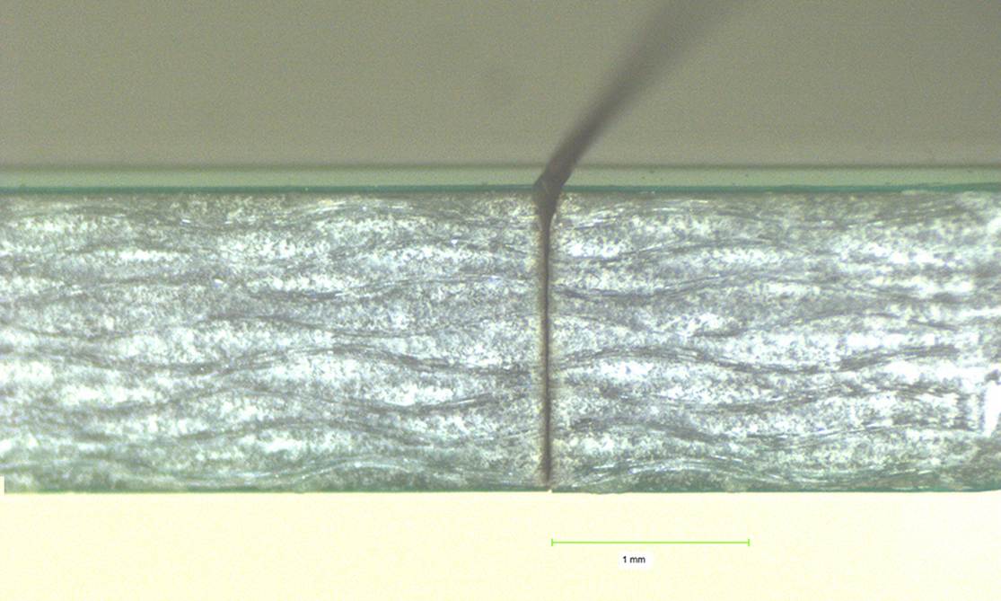
Kerf and heat-affected-zone measurement after multiple passes.
- Kerf: the width of removed material; measure at both entry and exit.
- HAZ: the zone where heat changed material properties or appearance.
- Taper: the difference between cut width on the two faces.
- Burr, dross and redeposition: material left on or around the edge.
- Roughness and microcracks: critical for functional or brittle parts.
- Repeatability: variation within a part, between parts and between batches.
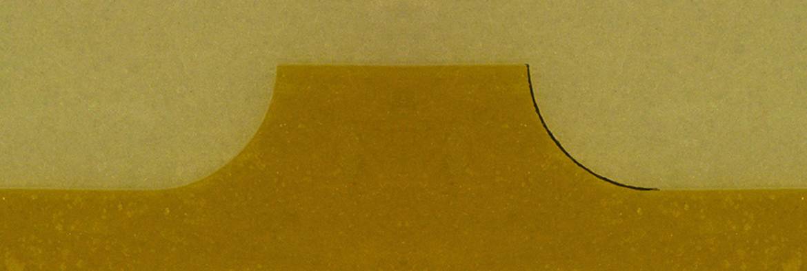
Parameter effects on copper and LCP polymer
| The useful selection criterion Do not compare only the maximum speed shown in a demonstration. Compare an acceptable result at sustained speed: edge quality, process stability, scrap, cleaning, consumables and real loading/unloading time. |
From laser source to production system
The source is only one part of the solution. A robust system combines beam delivery, optics, processing head, motion, fixtures, vision, enclosure, extraction, cooling, software, interfaces and documentation. APEL Laser can support application assessment, sample trials, configuration selection, integration, installation, training and service.
For more detail, read Coherent laser integration for industrial applications and review APEL Laser services.
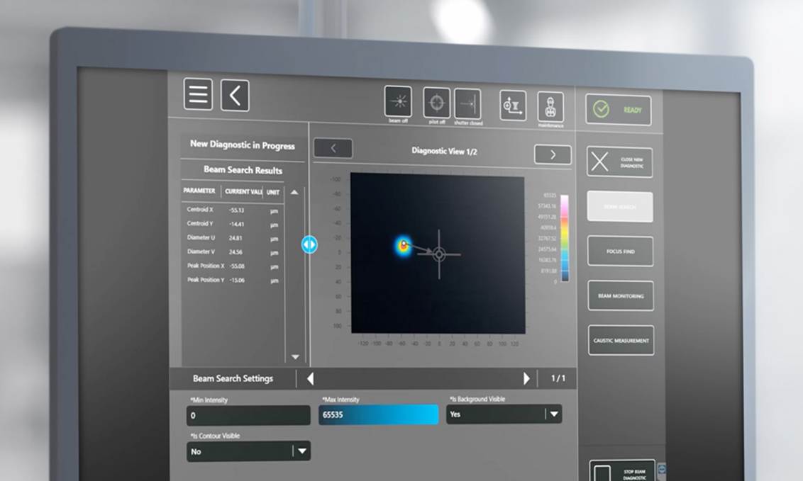
Software interface for process setup and control
Example solution
| Initial requirement | Direction to evaluate | APEL portfolio example |
| High-throughput metal cutting | Multi-kW fiber source with suitable head and motion | Coherent Edge FL |
| Precision cutting integrated in a line | Fiber subsystem with control and software | Coherent PowerLine FL |
| Organic materials / polymers | CO₂ at the right wavelength and power | Coherent DIAMOND C/Cx or J Series |
| Microfeatures, sensitive material | UV or ultrashort-pulse source | Coherent Rapid LX |
| Part requires a complete machine | Source + optics + motion + vision + safety | APEL-integrated configuration |
Useful product pages: Edge FL · PowerLine FL · DIAMOND C/Cx · DIAMOND J Series · Rapid LX · Q60 cutting system. Final configuration and performance must be confirmed for the customer’s material and process.
Recommended selection and validation process
- Define measurable requirements: material, thickness, drawing, tolerances, edge, HAZ, cycle time and volume.
- Select one or two laser families and a preliminary system architecture.
- Run representative samples, including real material and batch variation.
- Measure the output and confirm a process window, not just one successful parameter set.
- Engineer the integration: handling, fixtures, vision, extraction, safety, software, service and spares.
RFQ checklist
- fully identified material and, where possible, its technical datasheet;
- minimum, nominal and maximum thickness;
- 2D/3D drawing and part photographs;
- acceptance limits for kerf, HAZ, burr, taper and roughness;
- cycle time, annual volume, shifts and automation level;
- operations before and after cutting;
- automation interfaces, traceability needs and available space;
- safety, extraction and working-environment requirements;
- number of samples available for trials.
Frequently asked questions
What is the best laser for cutting metal?
A fiber laser is usually the first candidate, but thickness, alloy, reflectivity, edge requirements and throughput determine the configuration. Trials are still essential.
Can a CO₂ laser cut metal?
Some CO₂ systems process metals, but fiber technology is more efficient for many modern industrial metal-cutting tasks. CO₂ remains highly relevant for organic materials and many polymers.
When is a picosecond or femtosecond laser justified?
When microcracking, charring or HAZ must be minimized and the precision benefit justifies the investment and removal rate. The benefit should be demonstrated on the part.
Does more power always mean faster cutting?
No. Absorption, focus, material ejection, motion or edge-quality limits can dominate. Power that is not used effectively may only increase HAZ and cost.
Why are sample trials necessary?
Commercial materials vary in composition, coating, pigment, internal stress and thickness. Trials reveal the real process window and reduce investment risk.
What should be budgeted beyond the laser source?
Optics, head, motion, cooling, enclosure, interlocks, extraction, fixtures, vision, software, integration, installation, training, consumables and maintenance.
Validate the process before you invest
Send APEL Laser your material, drawing, thickness, edge requirements, cycle time and estimated volume. We can narrow the technology options, define trials and propose a system configuration that can be supported in production.
Request an application review or email sales@apellaser.ro.